 Honda Accord: Circuit Diagram
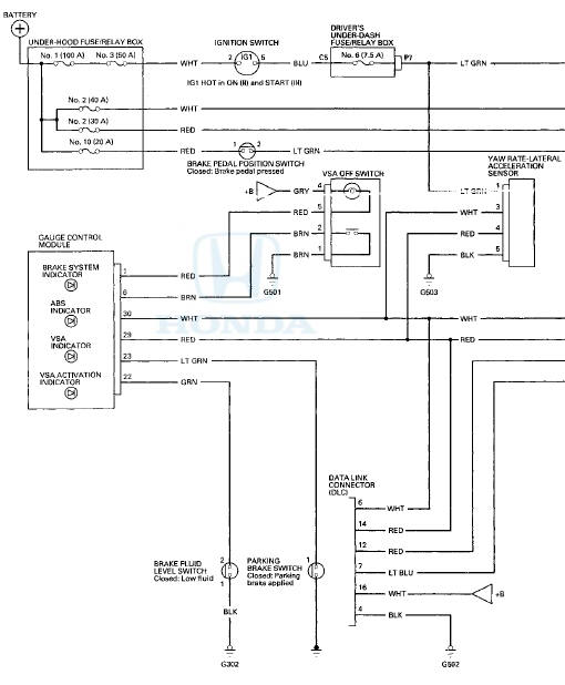

DRIVER'S UNDER-DASH FUSE/RELAY BOX CONNECTOR P (20P)

BRAKE PEDAL POSITION SWITCH 4P CONNECTOR

GAUGE CONTROL MODULE 32P CONNECTOR

VSA OFF SWITCH BP CONNECTOR

YAW RATE-LATERAL ACCELERATION SENSOR" 5P CONNECTOR

BRAKE FLUID 'LEVEL SWITCH 2P CONNECTOR'

PARKING BRAKE SWITCH 1P CONNECTOR

STEERING ANGLE SENSOR 5P CONNECTOR

WHEEL SPEED SENSOR 2P CONNECTOR

VSA MODULATOR-CONTROL UNIT 36P CONNECTOR

Wire side of female terminals
ECM/PCM CONNECTOR A (49P)

DATA LINK CONNECTOR (DLC)

Terminal side of female terminals
 System Description
VSA Modulator-Control Unit Inputs and Outputs for 36P Connector (Connector
Disconnected
Wire side of female terminals.
System Outline
This system i s composed of the VSA modulator-control u ...
 DTC Troubleshooting
DTC 11-13: Right-front Wheel Speed Sensor
Circuit Malfunction
DTC 13-13; Left-front Wheel Speed Sensor
Circuit Malfunction
DTC 15-13: Right-rear Wheel Speed Sensor
Circuit Malfunction
DTC 17-13: ...
See also:
Playing Internet Radio
Connect a compatible phone through Bluetooth®.
You can also connect the phone using your dock connector to the USB port.
Make sure the audio setting is correct for the connection type.
Press t ...
Transmission Removal
Special Tools Required
-Engine Hanger Adapter VSB02C000015*
-Engine Support Hanger, A and Reds AAR-T1256*
- Subframe Adapter VSB02C000016*
*: Available through the Honda Tool and Equipment
Progra ...